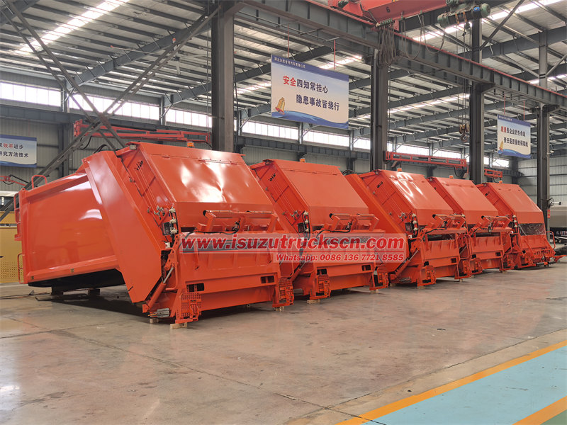
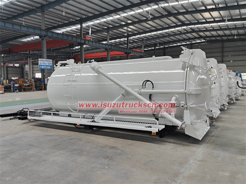
In recent years, an increasing number of global buyers choose a cost-effective customized solution: purchasing garbage compactor, hook lift garbage truck, sewage suction truck, and aerial work truck upper bodies from China, while matching with locally sourced ISUZU truck chassis. This combination greatly cuts procurement costs and shortens the delivery cycle. However, power take-off (PTO) installation is the core and most critical step in the entire vehicle refitting process, which directly determines the normal operation, working efficiency and service life of the upper hydraulic system.
Many overseas refitting technicians encounter common problems such as weak hydraulic power, abnormal noise, oil leakage and PTO damage after installation, most of which are caused by non-standard installation and incorrect debugging. As a professional manufacturer of special vehicle upper body, we will share a standard PTO installation guide for ISUZU chassis applicable to all mainstream special vehicle upper bodies, helping global customers complete high-quality refitting.
1. Basic Understanding: Why is the installation of the PTO on an Isuzu chassis so important?
The power take off (PTO) serves as the core power transmission component for the special vehicle upper body. It draws power from the gearbox of the ISUZU chassis and transfers it to the hydraulic pump, driving all upper body operations such as garbage compression for waste trucks, hook lift lifting, sewage suction, and lifting of aerial work platforms.

2. Pre Installation Preparation: Tools and Inspection
Thorough inspection and preparation before formal installation can effectively prevent rework and installation failures.
3. PTO Installation Steps for ISUZU Chassis
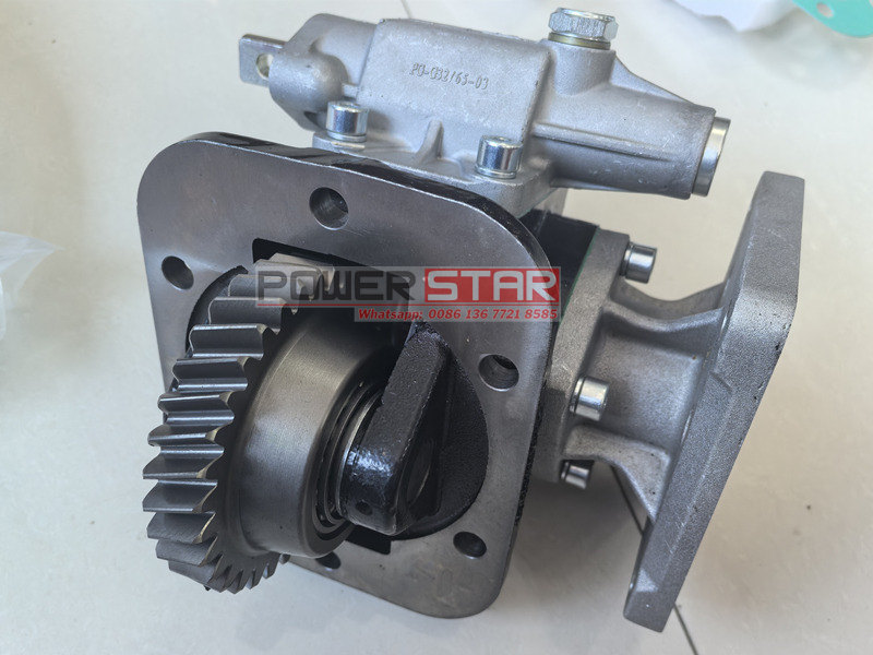
Ⅰ. Install the PTO
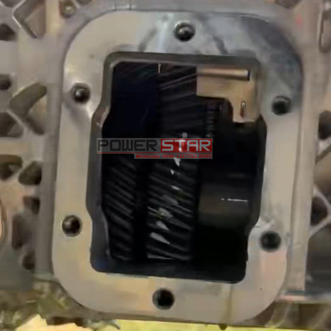
Step 1: Remove the gearbox cover


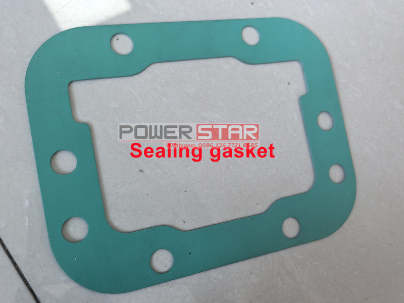
Step 2: Install the sealing gasket
Note that the surface in contact with the sealing gasket must be kept clean and free of dirt to avoid affecting the sealing effect.
Step 3: Connect PTO with gearbox

Ⅱ. Install the PTO cable
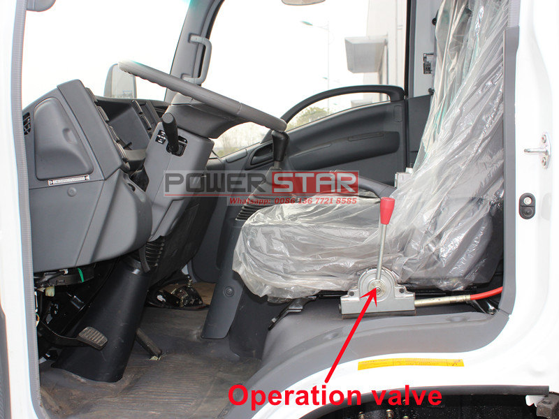
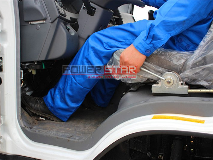
Step 1: Choose a suitable location to install the PTO cable, usually next to the seat or between the two seats, depending on your usage habits;
Step 2: After selecting the location, drill a hole in the cab, thread the cable through the hole, and fix the operating valve.
 |
 |
| Step 1 | Step 2 |
Step 3: Run the PTO cable through the chassis.
Note that when laying the cable, leave enough length so as not to affect the lifting of the cab.
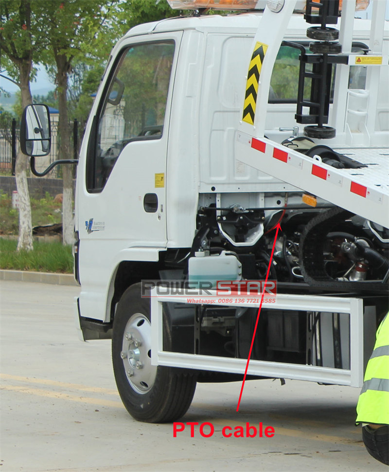
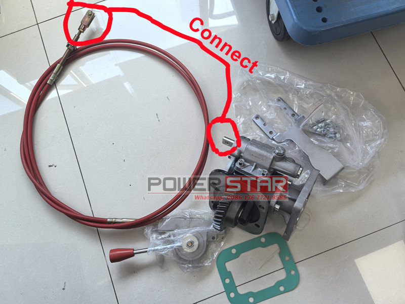
Step 4: Connect the cable to the PTO and fix it.
Note: The PTO cable installation section only demonstrates the installation method; the specific installation location needs to be determined based on the actual chassis conditions.


 |
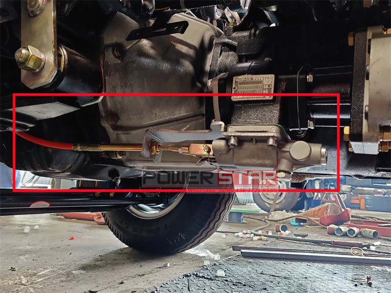 |
| Connect the cable with PTO | Fix the cable on chassis |
Ⅲ. Test the PTO
1. Start the engine, depress the clutch, and pull up or push down the PTO operating valve (depending on the customer's actual installation situation). The PTO will then start working.
2. Check if the power take-off (PTO) is working properly. If it is, the matching is successful.
3. Check the rotation direction of the PTO, whether it is clockwise or counterclockwise, to facilitate subsequent matching of the gear pump.
 |
 |