Isuzu GIGA water foam fire fighting vehicle built on a Isuzu giga heavy duty truck chassis, 380hp Isuzu 6UZ1 engine, FAST 12-shift gearbox, also called Isuzu giga rescue fire engine specifications, as the leader of modern firefighting equipment, combines high efficiency, versatility and advanced technology, and is an indispensable professional rescue tool for various fire scenes. This vehicle not only inherits the durability and excellent performance of the Isuzu brand, but also optimizes the design specifically for the needs of firefighting operations, ensuring rapid response and effective control of fires in emergency situations.
The Isuzu Giga Fire fighting vehicle is suitable for high mobility along the inner ways and can support without any damage extended periods of stand-by in full load conditions. The vehicle can operate in an environment where the ambient temperature could reach 55°C and with testing conditions of air, saline moisture and humidity.
The fully loaded vehicle has high stability and power to weight ratio in order to safely and speedily reach the fire by driving in narrow ways with sharp corners. The fully loaded vehicle has high acceleration and heavy duty braking system.
The controls are hydraulic, mechanical and electromechanical type, highly reliable and easy to maintain.
TYPE FIRE TRUCK
CHASSIS Isuzu GIGA – 6 x 4
CABIN SINGLE – 2 DOORS TYPE – 1+2 SEATS
TYRES FRONT SINGLE, REAR TWIN, SIZE 14 R 20
GEAR BOX MANUAL – FAST 12-shift YPE
Water agent capacity 10,000 lts
Foaming agent capacity 2,000 lts
Dry chemical powder capacity 150 kg
Example of internal seats lay-out
(Preliminary Layout)
Other detailed characteristics as per attached MAN technical documentation.
Front Axle capacity 7,500 kg
Rear Bogie capacity 13,000 + 13,000 kg (26,000 kg total) Gross Vehicle Weight Rating (GVWR) 33,000 kg
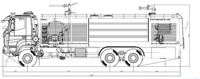
Overall length 10,000 mm (note: can be change during the engineering)
Overall width 2,500 mm
Overall height 3,418 mm (note: can be change during the engineering)
Wheel-base 5,100 mm (note: can be change during the engineering)
Make ISUZU GIGA
Model GIGA - euro 5
Type diesel 4-strokes direct injection turbo-charged
Location front
Cylinders 6 in line
Displacement 13L
Output power 280 KW (380 HP) @ 1900 rpm
Max torque 2’100 Nm @ 900 - 1400 rpm
Cooling system By water with tropical radiator and thermostat
Lubrication Fitted with oil pump and oil cooler
Maximum Speed 110 km/h (Electronically limited)
Battery 2 x 12 V
Capacity 175 Ah
Voltage 24 V
Gear box type Manual – MAN 16.25 OD type
Speed 16 speed
Position left-hand drive (LHD)
Type hydraulic
Front leaf spring hard type
Rear spring hard type
Shock absorbers on front & rear axles
Front single
Rear twin
Size 14 R 20
Design type road & cross-country
Service brakes full air pressure type double circuit , c/w ABS system
Parking brakes spring loaded type
Tank capacity 400 l
Fuel tank material steel
Location side type
Type Air conditioning System (std. MAN)
Location drive cabin
Jack, hydraulic one set
Wheels tools one set
Spare wheel & tire one, supplied loose.
Type Forward type, c/w hydraulic tilting device.
Seats driver’s + 03 crew seats – c/w seat belts (the 03 crew seats will be supplied with integrated SCBA holder)
Doors two (02)
Material Metallic frame work
Windshield & glasses The one-piece windshield ensures optimal all-around vision.
Drive section The Driver’s dashboard is fitted with every gauge and control necessary for safe drive.
· Speedometer with integral odometer.
· Tachometer.
· Fuel tank level gauge.
· Engine coolant temperature gauge (Celsius) and lubricating oil pressure gauge.
· Ammeter or voltmeter
· Dashboard illumination.
· Turning indicators and road hazard warning indicators
· Brake air pressure gauges with low pressure audible warning alarm.
· Main beam warning light.
· Air conditioning / heater/demister/vent controls.
· Headlights/dip, fog lights and sidelights switch.
· Windscreen wipers/washers controls.
· Engine stop control.
Fire section The controls of the fire-fighting system are located on a separate control panel which is accessible both from driver’s seat and officer’s seat and operator. It is well lighted for nocturnal operation and control and gauges have suitable labels in English. It encloses:
Switch and lamp for PTO 1 (Water pump engaged) siren switch
flash lights switch
pilot light for open shutters condition
(note: the above Fire section controls, commands and the positions can be change during the engineering stage and/or in accordance with the client specifications/requirements)
Fittings sun-visors
rear mirrors grab handles glove box
heater-demister-blower dome light
headlamps
front and side lights rear lights
fog lights road horn
Capacity 10’000 litres
Shape The tank is integral part of the body, has rectangular shape with reinforced side walls.
Mounting the tank is supported by a rigid skid, which is in turn mounted on the truck frame, by interposition of rubber shock-absorbers which prevent the transmission of torsion stresses from the frame to the tank itself.
Material Glassfibre Reinforced Polyester (GRP), thickness 8mm Fittings
cross-mounted anti-surge bafflers; longitudinal anti-roll bafflers;
manhole size 500 mm c/w quick open lid; overflow pipe, spilling safe;
Visual level gauge, electric type, at control panel in pump bay; suction sump with anti-swirl plate and strainer;
suction pipe with butterfly valve - manual
Capacity 2’500 litres
Shape The tank is integrated to the water tank, with dividing wall.
Material Glassfibre Reinforced Polyester (GRP), thickness 8mm
Fittings cross-mounted anti-surge bafflers, spaced less than 1 m and removable;
longitudinal anti-roll bafflers;
manhole size 500 mm c/w quick open lid; pressure and vacuum venting valve;
Visual level gauge, electric type, at control panel in pump bay; suction sump with anti-swirl plate and strainer;
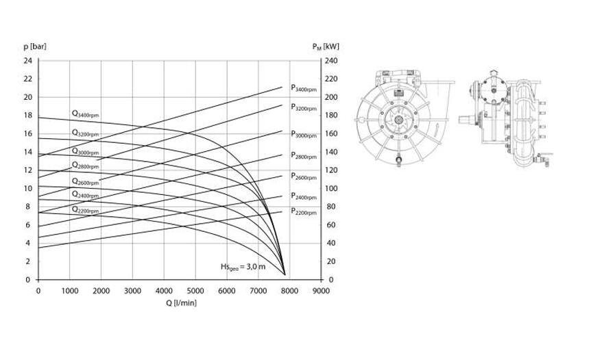
Model SWP 6’000
Pump performance Normal pressure 6,500 l/min @ 10 bar
Geodetic Suction height: -3 m suction height (suitable to suck up into the open/static
Pump: Single stage centrifugal pump (normal pressure)
Material: - impeller, pump casing and casing cover made of seawater- resistant Aluminium alloy
- pump shaft made from Stainless Steel
Drive unit: Drive by Chassis Engine Power Take Off (PTO 1)
Bearing: Maintenance free, oilfree
Shaft sealing: Mechanical seal, maintenance free
Priming system: VACUMAT, automatic air escape system, 0...8 m suction height, extra manual off, only working in time of suction, oilfree, maintenance free, pressure-less, rear pump construction
Safety unit: Thermical valve (overheating protection), pressure relief valve/overflow valve at high pressure part
Drainage: Drain cock on the lowest points of pump casing in order to drain off the water from pump casing, made of brass
Type fully automatic “Around the Pump” Foam System, generally meeting the requirements of NFPA 1901 code, where applicable. (installed in to by-pass of the fire pump), external suction (es. from Foam Concentrate jerry can), max. inlet pressure +0,5 bar (tank operation), easy handling, high mixing rates.
Foam Flow 500 lpm (using foam concentrates at 6%)
Proportioning ratio the proportioning ratio of each outlet will be selectable at any percentage from 1 up to 6 %.
Refill - Foam Concentrate inlets nos. 1 , c/w ball valve size 2” ½, manual type control and British
Standard BS336 type instantaneous coupling with strainer and non-return valve.
Foam Concentrate Drain / Outlet nos. 2 , c/w ball valve size 2” ½, manual type control and British
Standard BS336 type instantaneous coupling. (one co connections each left and right side)
Refill - Water inlets nos. 2 , c/w butterfly valve size 2” ½, manual type control and BSRT type. with strainer and non-return valve. (one connections each left and right side)
Water Drain / Outlet nos. 4 , c/w ball valve size 2” ½, manual type control and British Standard BS336 type instantaneous coupling. (two connections each left and right side)
Hydrant or open water suction inlets nos. 2 , c/w butterfly valve size 5" ½ manual type control and
BSRT type. (rear connections located in the pump bay)
Water/Foam pressure outlets nos. 4 , c/w ball valve size 2” ½, manual type control and British
Standard BS336 type instantaneous coupling. (two connections each left and right back side, rear mounted)
(note: the above Water/Foam inlets/outlets , type of couplings and the positions can be change during the engineering stage and/or in accordance with the client specifications/requirements)
Piping stainless steel 316L , TIG manually welded and passivated
Ball valves brass & chromium-coated sphere, PN 25
Butterfly cast iron & stainless steel disc
Connections Flanges or Victaulic joints
Couplings in Light Alloy
The above showed couplings are only for examples
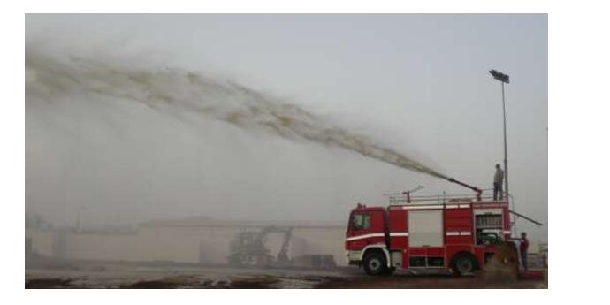
Model MCM 5000
Location located on the upper front deck
Service Water/Foam
Performance 4,000÷5000 l/min, @ 10 bar
Control Manual controls on top vehicle (by hand wheels)
Rotation 360° CW and CCW
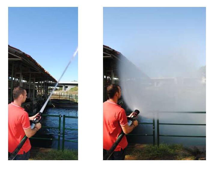
Throw Ranges Water = 75m
Water/Foam = 70m
Swivel 360°
Depression - 7°
Tilt + 75°
Materials Bronze body, bronze swivel parts and stainless steel ball bearing, stainless steel foam expansion pipe
(note: the above monitor configuration, can be change during the engineering stage and/or in accordance with the client specifications/requirements)
Construction the vehicle will be provided with two (02) hose reel, one for each side of the fire truck, fitted with brake, manual rewind crank and hose guide rollers where necessary.
Hose type non collapsible rubber hose
hose diameter 1”
Hose length 30 m
Nozzle type Pistol grip nozzle c/w 1” coupling, straight to fog pattern nozzle inbuilt Low expansion foam tube (expansion rates up to 12:1)
Discharge Automatic Nozzle, 475 l/min @ 7 bar
Design The vehicle is provided with
150 kg ABC dry chemical fire fighting unit
Position front mounted – between cabin & tanks
Vessel capacity: 150 kg
Vessel quantity 1
Vessel material Carbon steel
Design pressure: 16 bar
Working pressure: 14 bar
Test pressure: 21 bar
The vessel shall be fitted with:
pressure gauge refill plug size 4” inspection flange pressure relief valve drainage plug
Fluidising system the powder vessels have
an integrated system in order to fluidise the powder and prevent its stacking.
Pressurisation The pressurisation shall be made by means of nitrogen cylinders:
Quantity one (01)
Capacity, each 50 lts
Refill pressure 150 bar
Certificates The vessel shall be designed, made and tested according ASTM - ASME VIII.
The Nitrogen cylinders will be designed, made and tested according T PED
Fittings
individual pressure gauge nitrogen check valve
high pressure manifold high pressure main valve
pressure reducer 150 / 14 bar
vessel pressure valve. vessel vent valve, pipes flush valve
Construction the vehicle will be provided with two (02) first attack hose reels, fitted with brake, manual rewind crank and hose guide rollers where necessary.
Position side of powder tank, one on each side
Hose type collapsible rubber hose
Size 38 mm
Length 30 m
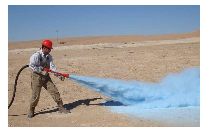
powder nozzle type Powder guns made of light alloy with internal parts of stainless steel
discharge 150 kg/min (2,5 kg/sec)
Throw approx. 8 – 10 m
10.
Pump control panel The control panel is located in the pump compartment - at rear side of the vehicle. It is well lighted for nocturnal operation. It includes:
- Water liquid tank level indication with remote signalling
- lamps at rear control panel;
- Foam liquid tank level indication with remote signalling
- lamps at rear control panel;
- Switch and lamp for Power Take Off (PTO 1) Water pump
- engaged
- Switch and lamp for water pump priming
- Switch and lamps for water/foam tank valves water suction/inlet pressure gauge
- water discharge pressure gauge
- foam proportioning control
- engine rpm/hours counter
- Driving controls (engine throttle)
- Emergency shutdown
Dry chemical unit control panel It is located near each dry chemical vessel - in the powder
system locker - and includes:
- nitrogen cylinders open / close control
- nitrogen hi – low pressure gauges
- high pressure nitrogen open / close valve
- vessel pressure gauge
- vessel pressurisation valve
- vessel vent valve
- flushing valves
Identification Control and gauges have suitable labels in English or internationally recognised pictograms.
(note: the above Lamps/Commands can be change during the engineering stage and/or in accordance with the client specifications/requirements)
Typical of Dry chemical control panel Typical of Water/Foam Pump control panel (Side installation) (Rear installation)
Design the water and foam tanks are integral part of the body work. The body is made from a rigid carbon steel structure, covered by Aluminium Alloy panels.
Material selection the selected materials will be suitable to operate in tropical climate conditions, with temperature up to 50 °C and humidity up to 100%
Construction lockers are provided at right and left sides; their walls and floor are made from aluminium alloy and they are fitted with suitable brackets for the auxiliary equipment; closures are made by aluminium roller shutters. Lockers are suitably lighted for nocturnal operation with automatic switches. Suitable stands are provided in order to assure easy access to the upper lockers; they are fitted with no- skid straps. The Dry Chemical systems are located into a wide-size compartment, giving protection but also easy access for maintenance and over-haul. It is closed by a roller shutter. The truck is fitted with heavy duty front bumper, steel made and fastened to the chassis frame. Mud guards are of galvanized steel, with rubber trimming and flaps
Brackets it will be quick release brackets, to ensure positive fixture and fast removal of the accessories delivered with the vehicle.
Shutters Dust and waterproof light alloy roller shutters all will be provided with a lock and key. Hose storage racks will be of sufficient width to accommodate hoses with suitable coupling with lugs extended.
Access The deck is boarded via one rear ladder.
Bumpers The truck is fitted with heavy duty front bumper, steel made and fastened to the chassis frame.
The traffic installation as per Manufacturer standard and according the national regulations.
12.2. Emergency lights & signals
Lockers lights Ceiling type, switching on automatically when doors are opened. Control panel light in the pump housing.
Radio Provisions shall be made for mounting a radio set, (the radio is not included in the supply).
Electrical Protection System Battery main switch Master switch Fuses box
Emergency signals n° 1 light bar with integrated flashing lights or rotating beacons on the cabin roof, colour red or blue
n° 1 flashing lights or rotating beacons on vehicle rear red or blue
Siren: n° 1 , 100 W two tone electronic siren
n° 1 , integrated PUBLIC ADDRESS System control
Surrounding lights n° 4 LED light on top side compartments (2 for left and 2 for right hand side)
Search Searchlight / flood light n° 2 , 24 Vdc mounted on the front of the cab, detachable type
c/w tripod and 30m reel cable
Example of cabin control panel with emergency signals & controls (in drive cabin)
Position Located on front vehicle bumper
Type Electrical driven 24V
Cable length 27 mt x 11 mm diameter, complete with hook
Rated Line Pull max 6800 kgs.
Remote Control Remote controlled switch with cable
14. FINISH
Mud-guards and under-frame The mud-guards and under-frame are coated with glossy
epoxy-bituminous product, also as noise suppresser.
Interior of steel profiles The interior of steel profiles is treated with oil and provided with
venting holes.
Light alloy panels The light alloy panel used both for the bodywork and the equipment lockers are self-protected against corrosion. However they receive an epoxy primer before the final painting. They are assembled to the steel structure by inter-laying an epoxy seal, which prevents rattling and humidity entry.
Ambient conditions The vehicle is suitable to operate in saline atmosphere, with high humidity and temperature.
Painting specifications
Colours
Epoxy primer 40 micron Poly-urethane enamel 60 micron Dry film thickness 100 micron
chassis MFR standard
body Red RAL 3000 (different colours can be made on request)
front & rear bumper White RAL 9010
shutter and walkway Aluminium natural colour locker inside Aluminium natural colour
water piping Green RAL 6018
foam piping Yellow RAL 1021
powder piping Red RAL 3000
Logo Custom made colours and scripts can be made on request.
Tire pressure labels Above the tires, in bar
Reflecting stripes The vehicles sides and rear are fitted with reflecting stripes for better visibility at night operations.
The following equipment shall be provided and properly mounted on the truck:
|
Q.ty |
Equipment |
|
|
|
|
|
Fire Hose |
|
04 |
Water Hard suction hoses – Ø 5” ½ – length 2,5 m – light alloy couplings BSRT stowed on the roof (suitable to suck up into the sea-water or a lake) |
|
02 |
Suction Strainers Ø 5” ½ – light alloy coupling BSRT |
|
10 |
Fire hoses 2” ½ x 30 m with 2” ½ instantaneous male/female hose couplings BS336 light alloy |
|
05 |
Fire hoses 1” ½ x 30 m with 2” ½ instantaneous male/female hose couplings BS336 light alloy |
|
|
Fire Nozzle |
|
04 |
Water nozzle (multipurpose type) – Ø 2”½ - full , fog & combination streams – light alloy couplings Ø 2” ½ inch BS336, capacity 1078 l/min at 7 barg (full jet) c/w additional foam tube for low expansion (expansion ratio up to 12:1) |
|
02 |
Medium expansion foam nozzle with light alloy couplings Ø 2” ½ inch BS336 (flow setting 400 lpm) made of aluminium stowed in racks |
|
|
Fitting/Coupling |
|
02 |
Dividing breeching with valves, inlet 1 x 2” ½ BS336 male light alloy coupling to outlet 2 x 2” ½ BS336 female light alloy coupling |
|
02 |
Adapter , inlet 2” ½ BS336 male light alloy coupling to outlet 2” ½ BS336 female light alloy coupling |
|
02 |
Adapter , inlet 2” ½ BS336 female light alloy coupling to outlet 2” ½ BS336 female light alloy coupling |
|
02 |
Adapter , inlet 2” ½ BS336 male light alloy coupling to outlet 2” ½ BS336 male light alloy coupling |
|
|
Hand tools |
|
04 |
firefighters suit made of nomex , jacket and trousers (the sizes will be defined later) |
|
02 |
(SCBA) Self Compressed Air Breathing Apparatus, single composite cylinder 6,8 lit @ 300 bar, CE/EN approved |
|
02 |
Pike head axe |
|
04 |
Fire hose bridge |
|
01 |
Portable heavy Inline foam inductor – 200 l/min @ 5 bar – adjustable mixing ratio 0–6%, light alloy couplings Ø 2” ½ inch BS336 |
|
01 |
Foam pickup tube for portable heavy Inline foam inductor, L=2 mt., light alloy couplings STORZ |
|
03 |
Portable Flashing Lamp lamps |
|
02 |
hose coupling wrenches/spanner for each coupling sizes |
|
|
Others equipment |
|
01 |
Portable megaphone |
|
01 |
Aluminium extended ladder (6m when extended) – stowed on vehicle roof |
Additional items:
|
Q.ty |
Equipment |
|
|
|
|
01 |
Foam decanting pump working by (24v) vehicle battery with hose it length about 10 m and rubber hose with immersion tube 70 cm |
|
01 |
powder filling funnel for 150 litres powder tank |
16.
QUALITY ASSURANCE SYSTEM CERTIFICATION
The vehicle will be designed, manufactured and tested according to ISO 9001: 2000
Documents The vehicle will be supplied complete with the following documents:
· Operation and maintenance of the chassis
· Vendor operations and technical manuals
· Spare parts lists for all vendor supplied equipment
· Engine technical and service manuals
· Electrical schematics
· Transmission technical and service manuals
· Service lubrication manuals Language English
Copies two
On request We can provide a technical and practical training course for 35 operators 2 week time in your premises for use and maintenance of fire truck.